TR-702 The level and audio loudness meter
Technical description and User manual
- Table of contents
- Short technical description
- Exploitation
Short technical description
This technical description and user manual are intended for technical staff working with the level and audio loudness meters TR-702-1 and TR-702-2 (hereinafter referred to as Devices).
Devices are designed and manufactured in accordance with:
- EBU R-128.
- ITU-R BS.1770-3.
- EBU Tech 3341.
- EBU Tech 3342.
- EBU Tech 3343.
- EBU Tech 3344.
- IEC 60297-3-100-2008.
Input (TR-702-1) and indicator (TR-702-2) units are intended only to work together and should be connected by patch-cord RJ-45 category no lower than 5e. The indicator unit is powered by the input unit in the normal mode via the same cable.
General information
The devices allow to measure the loudness level (analog or digital) of audio signals on the following parameters:
- M-loudness (instant loudness);
- S-loudness (loudness of short-term);
- I-loudness (integrated loudness);
- loudness range LRA.
The measurement results are displayed on the screen of the TR-702-2 unit.
In addition to measuring the loudness of the audio signal, the device also allows you to measure the signal level for each audio channel, and display it on the indicators with the dynamics of the classic peak/quasi-peak level of studio meter. Also, the device has correlometer with a custom width of integration window.
Technical characteristics
Input signals:
- balanced analog signal;
- digital AES/EBU signal;
- digital SPDIF signal;
- SDI signal (SD-SDI и HD-SDI).
| Parameter | Value |
|
Network transfer protocol |
proprietary |
|
Remote control |
by RJ-45 |
| Power TR-702-1 | Power Supply: In 220 V, 50 Hz Out +48В, 0,37А |
| Power TR-702-2 typical | PoE, 48V |
| Power TR-702-2 optional | Power Supply +5V, 2А (not included) |
| Power consumption (no more), W | 18 |
| Overall dimensions of the TR-702-1 unit (without rack mount brackets), mm | 145х218х43,6 |
| Overall dimensions of the TR-702-2 unit (without rack mount brackets), mm | 120х214х34 |
Input signal in digital formats AES and SPDIF support input streams with frequency 32/44,1/48 KHz. Input analog signal is digitized at 48 KHz. The maximum allowable amplitude of the input signal to an analog input - about 24 dBu. The noise level of the analog section of the device about –90 dBFS.
Contents of delivery
| № | Name |
Quantity, pcs |
| 1 | TR-702-1 (input unit) with mounting kit for installation in 19 "rack and Power Supply | 1 |
| 2 | TR-702-2 (indicator unit) with prop | 1 |
| 4 | Patch cord (category 5e) | 1 |
| 5 | Technical description and User manual | 1 |
| 6 | Packing | 1 |
Features
Block diagram
The block diagram of the device is shown in Figure 1:
Fig 1. TR-702. Block diagram.
The audio signals to be monitored are connected to the Input unit.
Input unit TR-702-1
The back panel of the TR-702-1 unit is shown on Figure 2:
Fig. 2 Back panel of the TR-702-1 unit.
The back panel of the TR-702-2 unit has the following connectors:
- On the left -2 XLR connectors (left, right) for analog signal;
- The third left XLR connector is used for input digital signal AES/EBU;
- S/PDIF digital signal is fed to the RCA connector;
- BNC connectors are input and output SDI signal, respectively;
- To update the firmware of the TR-702-1 unit, use the USB connector with the button on the right;
- RJ-45 connector for connecting to an Ethernet network for transferring data to the indicator unit and receiving commands from it;
- The top right connector is used to connect the unit to the power adapter.
Indicator unit TR-702-2
The unit is responsible for:
- Receiving audio streams via ethernet interface;
- Calculating of all measured and displayed values (levels, loudness, correlation);
- Displaing of level indicators and loudness;
- Interacting with the user via a touchscreen or mouse;
- Managing the operation of the calculator that reads the values of the indicators.
Main window
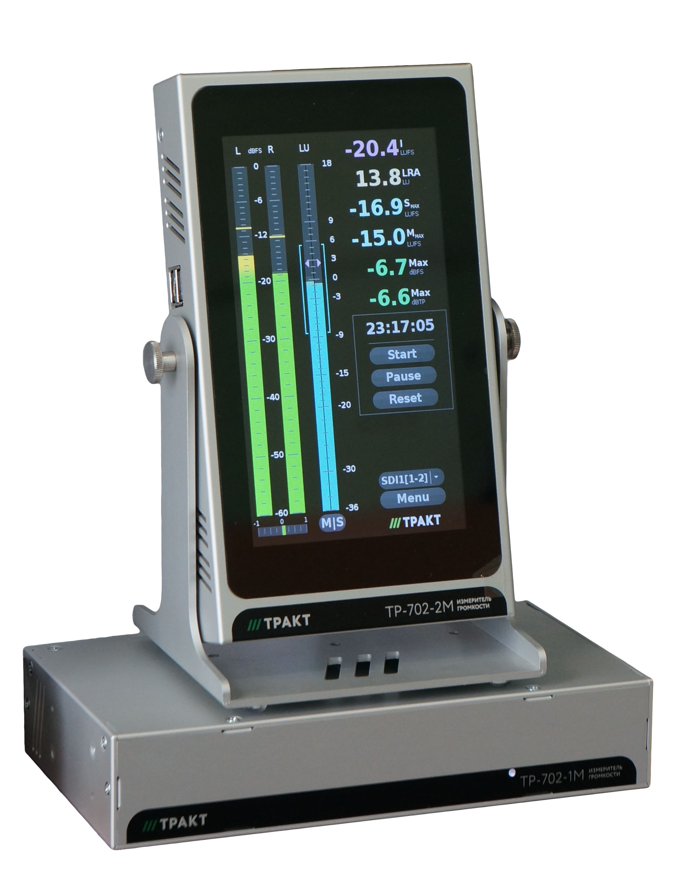
The appearance of the main window is shown in Figure 3.
Fig. 3 ТР-702-2. Main window
The main window is logically divided into three zones vertically.
In the left area of the main window there is a two-channel (stereo) peak level indicator, under it there is a correlation scale. Above the level indicators there is an inscription "dBFS"/"dBTP"/"dBu", which indicates the units displayed level.
In the middle area of the main window there is an EBU R-128 loudness indicator with a S/M loudness indication switch (Short-term/ Momentary loudness) under the scale.
In the right area of the main window are (from top downward):
- Windows displaying the integral values of the meter in numerical form (with an accuracy of 1 digit after the point):
- Loudness value (I-loudness according to BS-1770);
- Loudness range limits value (LRA by EBU Tech 3341: range /lower /upper),
- Maximums of M-loudness and S-loudness during the time from the last reset;
- Maximums of peak levels and true peak signal levels.
- Integration time from last reset in HH: MM: SS
- Three buttons START, PAUSE and RESET.
- Source selection button opens the input selection window for the loudness meter and peak indicators.
- Menu button opens a window for selecting options and editing device parameters.
Note: In accordance with the recommendation EBU Tech 3341, these buttons provide the following behavior of the meter:
- START - reset the integral values (I, LRA, Max-S, Max-M) and start the measurement.
- PAUSE - Stop and continue the process of measurement without resetting the integral value (meter can be in two states: active or stopped).
- RESET - Reset integral values without changing the state of the meter.
Window source selection
It allows to select the source of the displayed indicators. For a multichannel source, we indicate from which channels we take audio.
The window is the list of possible options. Only one can be active:
Stereo:
- Analog
- AES
- SPDIF
- Stereo - SDI[1-2]
- Stereo - SDI[3-4]
- Stereo - SDI[5-6]
- Stereo - SDI[7-8]
5.1:
- 5.1 - SDI[1-6]
- 5.1 - SDI[3-8]
Note: the list can be changed in accordance with the capabilities of the switch board and the input interface of the meter.
TR-702-2 Settings windows
When pressing the MENU button on the main window of the device, a window for selecting a settings page (or an information page) opens:
Fig. 4 TR-702-2 Settings windows
There are six pages:
- Analog input sensitivity Setting;
- Level Meter Settings;
- Loudness Meter Settings;
- Correlometer Settings;
- Statistics and status window;
- System settings window.
Most device settings are saved after turning the device off and on again.
IMPORTANT: Before disconnecting the indicator unit from the power supply, turn off the device with the button located on the system settings window. In order to preserve the integrity and quality of the storage media of the device, do not disconnect it from the power supply without a shutdown procedure.
Settings window of the level meter
The Settings window is shown in Figure 5.
Fig 5. The settings window of the level meter
In this settings window you can select:
- one of two used algorithms level measurement (Peak/TruePick);
- set the triggering dynamic of the indicator;
- set the return dynamics of the indicator;
- set the indicator scale and bind zero if it is calibrated in units other than dBFS;
- set the boundaries of coloring of color zones of indicator bars;
- set the presence of additional peak indicators on the columns ("caps") and their retention time.
Algorithms used to calculate the peak levels:
- Peak - search for the maximum of the digitized input stream (in the main window above the peak indicator the inscription "dBFS" is displayed);
- True Peak - the calculation of the peak signal levels with increased respiratory rate in 4 times and interpolation on the FIR filter (in accordance with the standard algorithm ITU-R BS.1770-3 Annex 2, while in the main window indicator marked "dBTP"). This algorithm is used only in the meter with the appropriate name.
Possible settings of the trigger dynamics of the level meter indicators:
- 0 - indicator of the unit responds instantly, even on a single sample in the input digitized stream;
- 5 ms / 10 ms - when the input sinusoidal signal is applied 0 dBFS with a packet of 5 ms/10 ms duration, the indicator bar reaches –2dBFS.
Possible settings for the return time of the level meter indicators:
- stepwise in the range from 0.5 to 5.0 seconds;
- The specified time is interpreted as a fall time of the column by 20 dB with the complete removal of the input signal. The fall rate of the instrument column is linear in dB.
Possible scales:
- relative scales in dBFS/dBTP units - 40/60/90 dB. The upper limit of dBFS scales is always 0dB, for dBTP scales there is an overflow zone of + 3dB.
- scales of typical devices, graded in dBu units. These scales are used only in the emulation modes of typical level measuring instruments (see below).
The last parameter on the page - "level zero" - is valid only for scales, graduated in dBu, and sets the zero position of the scale of the level indicator:
- Digital inputs - is given in units of dBFS in the range of the input digital stream device
- Analog input - set in dBu
The first selector on this setup page - "meter type" - has two groups of values.
The first group - universal indicators (Peak/True peak) - allows you to select an algorithm for calculating peak levels displayed on indicators, and manually adjust the scale and dynamics of the indicator by separate settings.
The second group - presets of typical studio level meters - influences many parameters at once, setting the values of the algorithm parameters, dynamics and scales for a device of a given type. For the second group, only the first level calculation algorithm is used (normal peak). The type of scale and the installation of the dynamics of the behavior of the indicator bar are preset. You can adjust only the zero position of the scale for scales graded in dBu.
All possible positions of the "meter type" selector are listed below:
- Universal (for these types, you can choose any of the dBFS scales, and any desired dynamics):
- Peak - adjustable peak/quasi-peak meter.
- True Peak - similar to the previous one, but with the "True Peak" algorithm, and the triggering dynamics are not adjustable (only inertia - "0").
- Presets of typical level meters (scale and speaker settings are fixed by a preset):
- DIN PPM - parameters are similar to popular DIN meter : response time - 5 ms, return time - 1.7 seconds, the scale - from –50 to +5 dBu;
- GOST1 - parameters are similar to popular GOST 21185-75 Type I meter: response time - 5 ms, return time - 1.7 seconds, the scale - from –40 to +4 dBu;
- GOST2 - parameters are similar to popular GOST 21185-75 Type II meter: response time - 5 ms, return time - 3.0 s, range - from –20 to +3 dBu;
- BBC - parameters are similar to popular BBC PPM meter: response time - 10 ms Reset time - 2.3 seconds, the scale - from –12 to +12 dBu steps 4dB;
- Inertionless - parameters are similar to meter used in the program DAW: instantaneous rise, return time - 1.7 seconds, the scale - 60dBFS.
Important information about the graduation of scales, the zero position of the scale and the correct reading of the measured levels:
The operation of a level meter with calibration and the use of scales is slightly different when used:
analog input;
any of the digital inputs - SDI, AES / EBU, SP / DIF.
When applying the test signal through an analog input, for correct operation of the device, it is necessary to calibrate using a test signal source (see details in the description of the system menu).
If one of the dBFS/dBTP scales is used with the selected level meter settings, then:
- for an analog input - zero of the scale corresponds to the set sensitivity of the device (selected on the separate settings page "Analog Input"). For example, if the sensitivity of the analog input is +15 dBu, then this value corresponds to the value 0 dBFS or 0 dBTP on the scale of the level meter;
- for digital inputs, the instrument displays the digitized input signal "as is". That is, the values in the SDI channel, or AES / EBU, exactly correspond to the digitization of the scale. Binding the dBFS scale of the input digital signal to the dBu scale (or other absolute scale) is external to the device.
If one of the scales calibrated in dBu is used with the selected level meter settings, then the zero position of the level indicator scale is set by the "zero level" parameter:
- for analog input - set in absolute units of input voltage dBu;
- for digital inputs - set in units of dBFS in the range of values of the input digital flow of the device, must be 0dBFS or less (negative value).
Settings window of loudness meter
Fig. 6 The settings window of loudness meter
In the main window, there is only one indicator showing the loudness - it displays M-loudness (by BS.1770-3) or S-loudness, which is controlled by the settings on this page of parameters, as well as by the button under the indicator on the main window.
One of the settings on this page controls the selection of one of the prescribed EBU R-128 (Tech3341) LU scales - or EBU +9 or EBU +18. A separate setting sets where the zero of the selected LU scale is on the LUFS scale.
Using the switches in the "displayed parameters" group you can turn on and off the digital readings of I-loudness, LRA, M-loudness and S-loudness maxima, peak level measurement results and/or true peak. These values are measured by the device taking into account the measurement history stored by the device. They are reset with the RESET and START buttons.
The I/LRA measurement interval parameter sets the depth of the instrument integration history of the I-loudness, LRA, and M-loudness and S-loudness maxima. History size can be set from 10 seconds to 24 hours. When the device reaches the set size of the history, it continues to measure four integral parameters, recalculating them for a set interval from the current point in time back to the set size of the history, that is, it switches to the "sliding integration" mode for the set interval. The time readings on the main window always correspond to the current size of the history, that is, they stop growing when switching to the "sliding mode". You can reset the status of the loudness meter at any time using the RESET or START button.
Note: the "depth of integration" parameter does not affect the peaks of the peak level measurement results and / or true peak, they always accumulate from the last pressing of the RESET or START button.
The other parameters on this page control the color marking of the bar, and the colors of the display of numerical indicators of the current values of I-loudness, LRA and maxima of M-loudness and S-loudness.
Note: The LUFS scale essentially corresponds directly to the dBFS scale for digital inputs. For analog input, the LUFS scale is connected to dBu via the analog input sensitivity switch.
Correlation settings window
Fig. 7. The correlation settings window
The correlometer has a single setting that allows you to set the size of the integration window for calculating the correlation coefficient from 100 milliseconds to 3 seconds.
Analog input sensitivity setting window
Fig 8. Window sensitivity setting of the analog input
The analog path and ADC of the device generates digital samples of a level of 0 dBFS with an input voltage of about + 24dBu. The noise level of the analog path and the ADC of the device, reduced to a maximum level of 0 dBFS, is about –92 dB. When using an analog input, the calculator cuts off all input signals with a level less than –84dBFS, so that the measuring algorithms (level, loudness, correlation) do not fall into the intrinsic noise of the analog path of the instrument.
Some types of peak / quasi-peak level indicators implemented in the device have scales calibrated in relative decibels (dBFS). For such scales, the decibel zero level is set by adjusting this settings page in dBu voltage units (i.e. decibels from 0.775 millivolts). The page is available and used only when the device is switched to using an analog input.
In addition to setting the sensitivity of the analog input, this page has a special reminder about the calibration of the instrument (see figure). To use the analog input device, it is necessary to calibrate it. If the calibration procedure has not been performed, or the device cannot find the calibration results, then this reminder appears. Calibration data is saved, as well as other settings, after the device is turned off correctly. The button for calling the CALIBRATION page is on the system settings page.
To calibrate the device input, a sinusoidal signal with a level corresponding to + 12 dBu is fed from the measuring generator, and the CALIBRATION button is pressed. After this procedure, the device begins to make the required corrections to all measured values, so that the level of 0dBFS on the relative scales of the device corresponds to the signal fed to the analog input with a level corresponding to the selected sensitivity.
Statistics and status window
Fig. 9. Statistics and status window
In this window, you can see the counters of good and bad UDP packets of the audio stream from the input module of the meter for monitoring the quality of the IP network and the ethernet connection between the input and computing modules.
Computing data is informational.
In the last section there is a measured sampling frequency of the input stream from the computing module.
System settings window
Fig. 10. System settings window
This window contains important general device settings and information:
- It displays the device firmware version, as well as the version of the exchange protocol with the input module, and the firmware version of the input module (if it is known);
- Button to turn off the power indicator device unit. After pressing this button, the device turns off after about 30 seconds and you can remove the supply voltage from it;
- Selection of the menu language, settings and the main panel of the device (Russian/English);
- Calibration button of the electronic path of the analog input device (input amplifier and ADC). The button is highlighted in red if the device has not been calibrated or reset;
- Section "Connection parameters": IP-address and port of the input module connected to the computing device (indicator unit); "UDP port" - a port on the computing device itself, where the input module sends audio streams; IP address and port on the indicator unit, connected to the input module.
Construction
The blocks are made in metal (aluminum) cases.
The TR-702-1 unit can be installed, both on the table and in the RACK 19 ’’ rack, with the help of special fixture corners. Connection of two blocks for more compact installation in a rack is possible.
The indicator block TR-702-2 has several mounting methods:
With U-shaped stand and screws included in the kit.
Using standard VESA75 and VESA100 mounts (not included).
For better visibility of the contents of the screen is provided by adjusting the angle of the indicator block.
The power supply of the TR-702-1 unit is carried out from the 220V network using an 48V adapter.
Power supply of the TP-701-2 unit can be carried out both through PoE (regular operation mode) and through an adapter 220V, 50Hz - + 5V, 2A (not included in the package).
The indicator is controlled using the touch screen.
Exploitation
Preparation
Preparation for work consists in the following actions:
- connect units TR-702-1 and TR-702-2 with each other
- supply power to the TR-702-1 unit
- send signals to the block TR-702-1
- select the signal source on the block TR-702-2
- after switching on and loading the device, on the indicator unit, by tapping the "Menu" button, you can call up the device settings page, and edit the necessary displayed parameters.
Transport and storage
Packaged units must be protected from installing other loads weighing more than 5 kg on them.
Compliance with other special conditions during transportation and storage is not required.
Operating instructions
Units must be protected from shock, ingress of dust and moisture.
Warranty
The manufacturer guarantees the operation of the devices, provided that users observe the conditions of operation, transportation and storage.
Warranty period of operation - 12 months from the date of transfer of the product to the consumer.
In case of violation of the terms and conditions of operation during the warranty period, the consumer is deprived of the right to free warranty repair or replacement.

